FEATURES AND BENEFITS
With high-speed relaying and 100% reliable transient free switching technology, the actiVAR mitigates voltage sag and voltage flicker, allowing large motors to start accross-the-line using simple motor starters. Say goodbye to complex VFD drives, synch bypass switchgear, their required E-House space, and all the complexities associated with this technology.
The following table summarzies the many features and benefits of applying the actiVAR to your system.
FEATURE |
BENEFITS |
Single-Cycle
Operation |
Provides near instantaneous mitigation of voltage sags and voltage flicker, resulting from large motor starting.
Near perfect voltage sag mitigation meeting voltage sag and voltage flicker requirements at your point of common coupling (PCC).
|
Solid-State
Valve Design
|
Transient Free Operation, eliminating adverse effects of switching transients.
|
Hybrid Designs For PF Correction
& Harmonic Filtering |
Corrects plant power factor, reducing KVA and power factor penalties, increasing system capacity, while improving your voltage profile.
Reduces plant voltage and current distortion. Designed for compliance with IEEE 519 harmonic distortion limits.
|
Metal-Enclosed Design |
All-Inclusive Design - Equipped with integral disconnecting device, protection, and control.
Comes fully assembled, calibrated, tested, and ready for interconnection.
Enclosure protects key components from wildlife and atmospheric contaminants.
Small footprint
Easy to maintain
Designed and built by an ISO 9001:2015 certified company with a proven track record of quality and performance.
Safety - Enclosure prevents inadvertent contact.
|
Key Interlock System |
Safety and proper sequence of operation
|
Simplicity |
Easy to purchase, startup, commission, and maintain.
Fully integrated design
|
RATINGS
NEPSI's actiVAR is rated and configured to meet customer requirements for voltage, basic insulation level (BIL), available short circuit current, reactive power rating, and frequency. Internal components such as disconnect and grounding switches, circuit breakers, capacitors, capacitor switches, DS1M switches, and capacitor fuses are chosen based on their ratings, costs, availability, and NEPSI's experience with the supplier's quality, service, and reliability.
RATING |
RANGE OF AVAILABLE RATINGS |
| Bank Configuration: | DS1M Switched: Single Step/Multiple Step
Hybrid Design: DS1M & static switched |
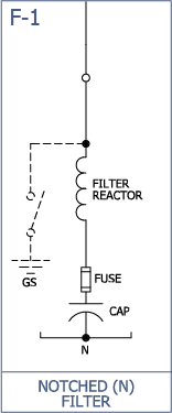
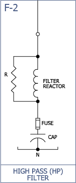
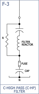
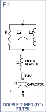
| Filter Types When Required: |
Notch (Band-Pass), High-Pass, C-High-Pass, Multi-Tuned, Notch, and De-Tuned |
| Operating Voltage (line-to-line): |
2.4kV – 24.9kV |
| Operating Frequency: |
50 Hertz | 60 Hertz |
| Reactive power output: |
0.5MVAR – 100 MVAR
(500kvar – 100,000 kvar) |
| Tune frequency (Hz) |
85 Hz 2100 Hz
(1.4th Harmonic – 35th harmonic) |
| High-Pass (damping) resistor rating: |
1 ohm to 1000 ohms
10kW/Phase - 200kW/Phase |
Short circuit
(asymmetrical momentary): |
16kA - 61kA |
Impulse withstand voltage
(Basic Insulation Level): |
60kV – 110 KV |
Short-time withstand voltage
(1 minute 50/60 Hertz): |
19kV – 38kV |
| Control voltages: |
AC Volts: 110, 115,120, 220, 50/60hz
DC Volts: 24, 48, 110, 125, 220 |
| Operating temperature range: |
-50°C to +55°C
-58°F to 131°F with supplemental heating/cooling |
| Maximum altitude without de-rating: |
1,000 Meters
3,300 Feet |
| Enclosure: |
(NEMA): 1, 3R, 4X, 12
(IEC): IP10, IP14, IP56, IP52
Arc Flash Mitigation: Passive & Active
Hazardous Locations: NEC Class 1 & 2, Div. II |
| Seismic: |
As specified - Zone 4 |
| Capacitor fusing: |
Internally fused | Externally fused |
| Performance Standards: |
SEMI (Semiconductor Equipment and Materials International), F47-0706, F49-0200, and F50-0200s
CBEMA (Computer and Business Electronic Manufacturers Association), curve referenced in ANSI/IEEE Std. 446-1987
ITIC (Information Technology Industries Council) tolerance curve
IEEE Standard 1346-1998, Recommended Practice for Evaluating Electric Power Systems Compatibility with Electronic Process Equipment
IEEE 1250-1995, Guide for Service to Equipment Sensitive to Momentary Voltage Disturbances.
IEC 61000-4-11 and 61000-4-34, (International Electrotechnical Commission)
IEEE Std. 1453, Table A.1, Recommended Practice for Measurement and Limits of Voltage Flucations and Associated Light Flicker on AC Power Systems
IEEE 519, Recommended Practices and Requirements for Harmonic Control in Electrical Power Systems
|
COMPONENTS
Component selection is based on specified control and protection requirements, DS1M switched and conventionally switched harmonic filter bank requirements, short circuit level, voltage, BIL, reactive power rating, frequency, costs, and NEPSI's experience with component quality and reliability. The following list provides key components and features commonly supplied by NEPSI.
Click each of the headings below to learn more about our commonly used components
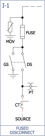
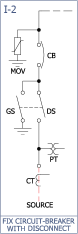
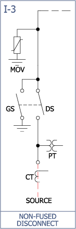
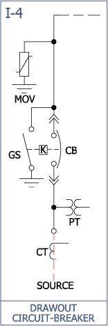
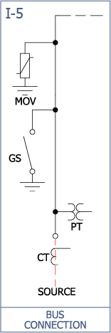
 INCOMING COMPARTMENT
Air Disconnect Switch
Externally operated chain-drive operated 3-pole air-disconnect switch to provide a "visible-break" and electrical isolation of the equipment during maintenance and repair.
Ground Switch
Externally operated chain-drive or direct-drive operated 3-pole ground switch to ground the load-side terminals of the incoming air-disconnect switch, breaker, and/or capacitors for safety during maintenance. The ground switch is key interlocked with the upstream disconnecting device to prevent closing of the ground switch onto a live bus.
Main Incoming Fuses
Main incoming current limiting fuses (with local and remote blown fuse indication) for short circuit protection of the equipment.
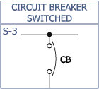
Main Incoming Breaker
Main incoming drawout or fixed-mounted circuit breaker for protection, isolation, and switching of the equipment.
Lightning Arresters
Lightning arresters are provided as standard on NEPSI's equipment to protect the actiVAR and incoming cables from lightning and switching transients.
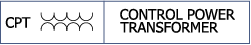
Control Power Transformer(s) (CPT)
Control power transformers to supply control power and voltage sensing to the DS1M switched stages, metering, protection, and control system.
Current Transformers (CT)
Current tranformers to supply a current signal for the metering, protection, and control system.
Bus Duct Entry
Bus duct entry to allow for direct bus connection to switchgear.
Dead-Front Entry
Dead-front design entry that allows for 200 amp and 600 amp separable elbow connectors.
Roof Bushing Entry
Roof bushing entry to allow for direct connection to overhead bus within substations.
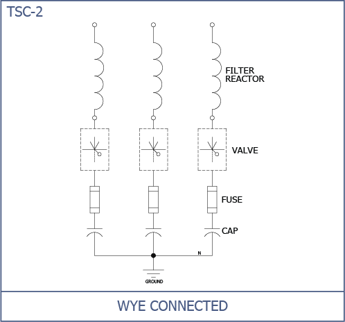
 DS1M-SWITCHED & CONVENTIONALLY-SWITCHED FILTER COMPARTMENTS
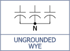
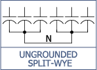
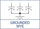
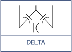
Capacitors
Low loss, double bushing capacitors that meet or exceed IEC 871, IEEE 18 and CSA standards. Capacitors are typically connected ungrounded-wye or ungrounded split-wye for conventionally switched filter stages and wye-grounded and delta connected for DS1M switched harmonic filter stages. Internal discharge resistors reduce the residual voltage to less than 50 volts within 5 minutes of de-energization. The dielectric fluid is environmentally friendly, biodegradable, non PCB, with low toxicity. Internally fused capacitors are available upon request.
Capacitor Fusing
Capacitors are individually fused with current limiting fuses. These fuses reduce the possibility of case rupter on capacitor failure and allow the system to continue to operate when a capacitor fails. The fuses are equipped with blown fuse indicators and can also be equipped with direct fuse operation sensors for blown fuse detection.
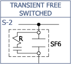
DS1M Switches
DS1M-Switched filter stages utilize DS1M switches to achieve instantaneous and transient-free switching.
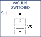
Capacitor Switches
Conventionally switched harmonic filter stages are equipped with vacuum contactors (for voltages less than 6.6kV), capacitor switches, or circuit breakers (fixed or drawout) for stage switching.
Iron Core Filter Reactors
Iron-core filter reactors provide the necessary inductance (inductive reactance) to tune the conventionally switched and DS1M switched stages to the desired frequency. In addition to tuning, the reactors significantly reduce the frequency and magnitude of the switching transient.
High Pass Filter Resistors
Stainless steel Grid Reistors are provided for C-High Pass, High-Pass, and Double-Tuned conventionally switched harmonic filter stages. Resistors are of a stainless steel stamped grid design that offer compact high wattage capability, low temperature coefficient, and corrosion resistance.
Current Transformers
Harmonic filter stages can be equipped with current transformers to provide a current signal for metering and protection. Current transformers can be provide to monitor both iron-core reactor current as well as high-pass resistor current.
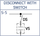
Air Disconnect Switch
Externally operated, key interlocked, 3-pole air-disconnect switch(s) that isolates a single stage of a multi-stage filter bank, allowing for partial bank operation during maintenance.
Ground Switch
Externally operated, key interlocked, 3-pole ground switch(s) that grounds the capacitor terminals to ensure all trapped charge has been removed from the capacitors.
 CONTROL AND PROTECTION COMPARTMENT
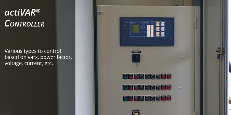
actiVAR Controller
The actiVAR is equipped with a speciallized microprocessor controller that has the necessary speed and software for controlling the DS1M switches for voltage and flicker mitigation. The controller also incorporates the conventionally switched harmonic filter stages for power factor correction.
Protection
DS1M Switched and conventionally switched filter stages may be equipped with various protection relays, meters, and sensors to protect the filter stages as well as the system from over-voltage, out-of-balance operation from capacitor failure, internal faults, and over-temperature due to fan failure. Protection devices are integrated with the actiVAR controller to form a fully integrated system.
Arc Flash Mitigation
See NEPSI’s technical note on arc flash mitigation in metal-enclosed capacitor banks and harmonic filter banks. This technical note provides over 30 mitigation strategies available from NEPSI to minimize the level of exposure to arc flash events as well as ways to reduce the probability that an arc flash event will occur in the first place.
 MISCELLANEOUS
Enclosure
Free standing, compartmentalized, all welded, 11 gauge galvanneal steel construction with 3 point pad-lockable latching handles and stainless steel hinges. The enclosure is painted with Engineered Siloxane, a Marine paint with rated salt spray of 5500 hours. NEMA 3R (IP64) construction is standard, NEMA 12 (IP65) and 4X (IP66) are available as an option. Base of enclosure as well as capacitor supports are formed from C4 structural steel. Door stays and windows are standard.
Key Interlock System
Key interlock system are available that dictate sequence of operation and safe entry into the enclosure. Upstream devices may be included in the interlock sequence.
Ground and Phase Bus
A 1/4" X 2" Tin plated ground bus is provided through the width of the enclosure to assist in grounding during maintenance. All phase bus is Tin plated square edged and rated at a minimum of 135% of the bank nominal current rating.
PROTECTION
NEPSI's actiVAR is furnished with an integrated control and protection system that is located in an isolated compartment that is integral with the equipment enclosure or located remotely in an E-house or control room. Whether integrally mounted, or remotely located, NEPSI's control and protection systems are completely tested, set, and calibrated at the factory before shipment.
All stages, whether conventionally or DS1M switched, are protected against short circuit, overload, over-voltage, harmonic over-current, harmonic over-voltage, over-temperature, and unbalance operation from blown capacitor fuses. Protective relays and ancillary protective devices are chosen based on function, cost, reliability, and customer preference.
The Table below summarizes the protection devices that are typically provided with NEPSI’s actiVAR.
PROTECTION TYPE |
DESIGNATION |
PROTECTION DESCRIPTION |
Short Circuit and
Overcurrent Protection |
50/51
50/51G |
Provided by the upstream feeder breaker, the main incoming breaker (if provided), or main incoming current limiting fuses (if provided). |
| Over-Voltage |
59 |
Provided to protect the actiVAR as well as the power system from over-voltage. This system provides backup to the actiVAR and PFC control which uses voltage as a primary or secondary control input. |
| Under-Voltage |
27 |
Under voltage protection system is provided to disconnect the actiVAR in the event of a power interruption as well as to detect an actiVAR control malfunction. |
Neutral Unbalance
(Blown Fuse Detection) |
59N or 51N or
51G or Direct |
Relay or direct fuse sensing to detect a capacitor fuse operation. This protection is critical as a blown fuse condition will result in filter de-tuning, lower var output, lower performance, and possible system resonance. |
Harmonic Voltage &
Current Distortion |
Ithd, Vthd |
Protection against harmonic resonance, high voltage & current distortion, and harmonic overload. |
| Over-Temperature |
26 |
Over-temperature protection for the DS1M switches, capacitors, and iron-core reactors. Also protects agains fan failure. |
| Over-Load |
49 |
Over-load protection of the harmonic filter, high-pass resistors (if provided), iron-core reactors, and DS1M switches. The overload relay is sensitive to RMS current associated with the filter's fundamental current and harmonic current. |
| Arc Flash Protection |
-- |
ABB UFES System; arc flash protection relay and ultra fast earthing switch to eliminate arcing faults in less than 4 mS. See NEPSI’s arc flash mitigation document for further details on arc flash mitigation. |
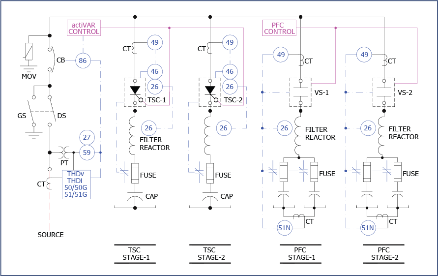
TYPICAL PROTECTION SYSTEM
The drawing below shows a typical relay protection diagram for an actiVAR with conventionally switched filter stages. The "actiVAR" control and the DS1M switched stages provide "fast" vars for voltage sag and voltage flicker mitigation. The "PFC" control and "PFC" stages provide "slow" vars for power factor correction, harmonic filtering, and general var support.
CONTROL OPTIONS
NEPSI's actiVAR system is furnished with a fully integrated control and protection system. It utilizes off-the-shelf SEL487V custom programmed relay that quickly and efficiently controls the ABB's DS1M Switches and conventionally switched power factor correction and harmonic filter stages (when present) to correct power factor and mitigate voltage sags. Because the control and protection system is based on Schweitzer Engineering Laboratories relay technology, plant maintenance people are able to maintain, adjust, and access the relay and its program without having to call the manufacturer - a big plus for the actiVAR when compared to VFD drive motor starters.
The control system consists of a DS1M controller (SEL487V relay), key interlock system, and other metering, control, communication, and indication devices that are necessary for the safe, proper operation, and monitoring of the entire system.
STANDARD
FEATURES |
| DS1M-Switched stage control for dynamic voltage control |
| Conventionally-Switched stage control for power factor control and harmonic mitigation |
| Fully integrated HMI display |
| Integrally mounted or remotely located control panel |
| Remote access to all controller functions |
CONVENTIONALLY SWITCHED STAGE CONTROL OPTIONS |
| Power Factor Control |
| Var Control |
| Voltage Control |
| Harmonic Voltage / Current Distortion Control |
| Remote / SCADA Control |
HOW TO ORDER
Please reach out to NEPSI via email to sales@nepsi.com to begin the ordering process.


Follow us on social media for up-to-date news, videos, and other information: