CALCULATION OF TOTAL HARMONIC CURRENT DISTORTION
The following calculator computes the total harmonic current distortion (THDc), Peak Current, RMS Current, and Crest Factor based on individual harmonic current distortion values between the 1st and the 50th harmonic. Input the fundamental current and individual harmonic currents to compute THDc also to view a waveform plot based on the input values. The waveform plot assumes all phase angles for individual current distortion values to be zero degrees (in phase with the fundamental current).
When inputting the data, be sure to use consistent units of Amps, or Per Unit Amps.
Of Interest...
Total Harmonic Current Distortion (THDC) of a current signal is a measurement of the harmonic distortion present and is defined as the ratio of the sum of the power of all harmonic current components to the power of the fundamental frequency current. THDc is used to characterize the power quality of electric power load and the current flowing in your system's conductors. Distortion factor is a closely related term and is sometimes used as a substitute term.
IEEE 519, "Recommended Practices and Requirements for Harmonic Control in Electrical Power Systems" provides suggested limits for harmonic current distortion as shown in Tables 10.1, 10.2, and 10.3 below. The tables are dependent on several variables and concepts defined as follows:
- PCC: Point of common coupling. This point is defined as the point in the utility service to a particular customer where another customer could be connected. It is often chosen as the utility metering point.
- ISC: Available short circuit current.
- IL: 15 or 30 minute (average) maximum demand current.
- TDD: Total demand distortion. TDD is identical to THD except IL (as defined previously) is used instead of the fundamental current component.
- ISC/IL: Ratio of the short circuit current to the demand current.
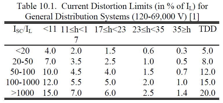
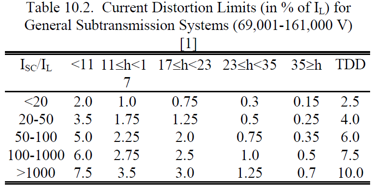
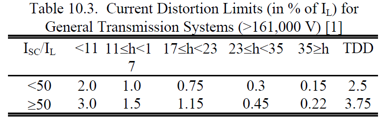
The thought processes behind the development of these tables are that 1) the customer should be responsible for limiting harmonic currents in accordance with Tables 10.1, 10.2, and 10.3 and 2) the utility should be responsible for limiting harmonic voltage in accordance with Table 10.4 as presented on our calculator page for harmonic voltage distortion.
Crests Factor is a measure of a waveform showing the ratio of the peak value to the RMS value. A crest factor of 1.0 indicates no peaks, such as the case with DC Voltage. A voltage waveform with 0% THD will have a crest factor equal to 1.414. Crest Factors greater than 1.414 usually indicates the presence of harmonic distortion.
Calculator
Known variables: Fundamental Frequency Amps, Harmonic Amps
