The following calculator computes the resistance, inductance, inductive reactance, capacitance, charging current, and surge impedance for medium voltage shielded power cables. This calculator provides a good estimate based on industry standard calculation methods and cable manufacturing data. Typical data, when your specific data is not available, is provided in Table-1 through Table-3.
Calculator-1
Known variables:
Cable Data: Length (feet), Conductor Diameter (inches), Cable Insulation Thickness (inches), Insulation Dielectric Constant, and Operating Frequency (Hertz), and Voltage (kV). When data is not available, use Table-1 through Table-3 for representative values
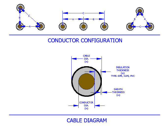
Cable Installation Detail: Cable Spacing (see figures below) A, B, C, and Correction Factors for Type of Installation (See Table-4)
Conductor Operating Temperature (°C): For cable operation at temperatures other than 20°C, enter expected operating temperature
Calculated Output: Cable Diameter, Total Capacitance (uF), Total Charging Current (Amps), Charging Vars per phase (kVAR), Charging Reactance (Mohm*1000 ft), Inductance (mH), Reactance (ohms), AC Resistance, X/R ratio, and Surge Impedance (ohms).
Basis of Calculation
Capacitance of Cables, Charging Current, and Charging Reactive Power
The capacitance of a one conductor shielded cable is given by the formula below:
Where:
| C = Total capacitance of the cable (microfarads) | Icharge = Charging current of the cable |
| SIC = Dielectric constant of the cable insulation (Table-3) | D = Diameter over the insulation (in) |
| d = Diameter of the conductor (in) | VLL = System operating voltage in (kV) |
| f = System operating frequency (Hz) | L = Length of the Cable in Feet |
| Icharge = Charging current (amps) | KVARcharge = Single-phase KVAR or charging VARs per cable |
Inductance and Reactance of the Cable
The inductance and inductive reactance of three single phase cables is provided by the formulas below. The formulas assume a cable configuration as shown in the figure above. Additionally, since the inductance is dependent upon its material surrounding, use Table-4 to determine an appropriate "K" factor (multiplier) for the inductance.
Where:
| XL = Conductor inductive reactance (ohms) | LC = Cable Inductance (mH) |
| L = Length of the Cable in Feet | A, B, C = Spacing per the figure above (in) |
| K = Installation correction factor shown in Table-4 | d = Diameter of the conductor (in) |
Cable Resistance at Operating Temperature
The resistance of the conductor is provided at 20 deg.C in Table-1. When operating at a different temperature, the resistance varies and is given by the following formula:
Where:
| RAC = AC resistance of the conductor at operating temperature (ohms) |
| RAC20C = AC resistance of the conductor at 20°C (ohm) |
| T = operating temperature of the conductor (°C) |
Surge Impedance
The surge impedance of the cable can be calculated with the following formula:
Where:
| Zo = Surge Impedance of the Cable (ohm) |
| LC = conductor inductance (mH) |
| C = total capacitance of the cable (microfarads) |
