Basis of Calculation
This calculator provides the initial voltage drop and voltage sag at the motor terminals and at the primary side of the supply transformer based on source impedance data and motor nameplate data. All impedance data is converted to per unit impedance values on the motor's base KVA rating (these values are shown in the calculator). Motor impedance data is determined based on the locked rotor current and starting power factor. This information is available on the motor data sheets or can be obtained from the motor code letter provided on the nameplate of the motor (use the table to determine locked rotor current based on motor code letter).
A voltage divider is used to calculate the expected voltage at the motor and at the transformer primary. The calculator does not account for dynamic effects of adjacent motors and generators.
Use this calculator to obtain the approximate actiVAR MVAR rating required to meet your performance requirements. Generally, the actiVAR will need multiple steps to meet performance requirements during turn off as the motor accelerates to rated speed.
Code Letter for Locked Rotor Current
(kVA/HP ~ Per Unit Full Load Amps) |
| Code Letter | Per Unit Multiplier | Code Letter | Per Unit Multiplier | Code Letter | Per Unit Multiplier |
| A | 0.00 - 3.14 | H | 6.30 - 7.09 | R | 14.00 - 15.99 |
| B | 3.15 - 3.54 | J | 7.10 - 7.99 | S | 16.00 - 17.99 |
| C | 3.55 - 3.99 | K | 8.00 - 8.99 | T | 18.00 - 19.99 |
| D | 4.00 - 4.49 | L | 9.00 - 9.99 | U | 20.00 - 22.39 |
| E | 4.50 - 4.99 | M | 10.00 - 11.19 | V | 22.40 AND UP |
| F | 5.00 - 5.59 | N | 11.20 - 12.47 | | |
| G | 5.60 - 6.29 | P | 12.50 - 13.99 | | |
Of Interest...
A starting motor appears as a large load with very poor power factor, which improves as the motor approaches full speed. Depending on the motor, this may take from two seconds to one minute. The effects from these starts may be reduced in the following ways:
- By starting the offending motors during noncritical periods
- By not turning them off as often and thus not having to start them as often
- Using reduced-voltage starters (RVSS, RAVT auto-transformer)
- Using low distortion variable speed drive (VSD)
- Using the actiVAR
All electric power utilities set specific limits on the allowable voltage sag during motor starting at the point of common coupling (PCC). These limits are set regardless of the projected plant conditions or loading profiles and are enforced to insure the quality of power distribution grid and to minimize complaints from other customers supplied from the same distribution network.
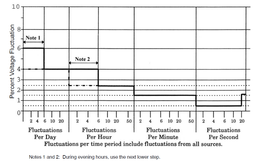
Utility Limit
The figure below provides a typical chart showing voltage sag limits that may be required by a serving utility. The chart shows a voltage sag limit of 4% or 6% for 1 to 6 fluctuations per day depending upon the time of day. These sag limits would typically be applied at the point of common coupling (PCC) and will vary with each utility. Check with your utility to obtain your limits.
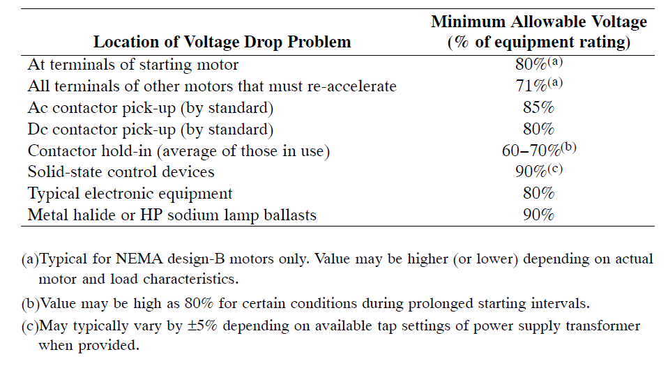
Facility Limit
In general, commercial and industrial customers are allowed as much self-induced voltage sags and voltage flicker as they can tolerate, as long as they do not impact other customers. Voltage sags and flicker can be greater than limits allowed by the local utility at the PCC. The allowable limits are based on the sensitivity of the load and will vary from site to site and with type of load.
As a guideline in identifying potential problems at your facility, Table 1 below indicates the sensitivities of some common devices to voltage sags and voltage flicker.